1-13
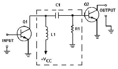
Figure 1-11 shows an impedance-coupling network between two stages of amplification. L1 is the
load for Q1 and develops the output signal of the first stage. Since the d.c. resistance of a coil is low, the
efficiency of the amplifier stage is increased. The amount of signal developed in the output of the stage
depends on the inductive reactance of L1. Remember the formula for inductive reactance:
Figure 1-11.—Impedance-coupled transistor amplifier.
The formula shows that for inductive reactance to be large, either inductance or frequency or both
must be high. Therefore, load inductors should have relatively large amounts of inductance and are most
effective at high frequencies. This explains why impedance coupling is usually not used for audio
amplifiers.
The rest of the coupling network (C1 and R1) functions just as their counterparts (C1 and R2) in the
RC-coupling network. C1 couples the signal between stages while blocking the d.c. and R1 develops the
input signal to the second stage (Q2).
Transformer Coupling
Figure 1-12 shows a transformer-coupling network between two stages of amplification. The
transformer action of T1 couples the signal from the first stage to the second stage. In figure 1-12, the
primary of T1 acts as the load for the first stage (Q1) and the secondary of T1 acts as the developing
impedance for the second stage (Q2). No capacitor is needed because transformer action couples the
signal between the primary and secondary of T1.

