3-54
View (A) shows that during the first half cycle of load voltage, current flows through CR1, the load
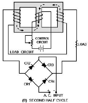
coils, and CR3. View (B) shows that during the second half cycle, load current flows through CR2, the
load coils, and CR4.
Figure 3-39A.—Simple full-wave magnetic amplifier. FIRST HALF CYCLE
Figure 3-39B.—Simple full-wave magnetic amplifier. SECOND HALF CYCLE
Up to this point, the control circuit of the magnetic amplifier has been shown with d.c. applied to it.
Magnetic-amplifier control circuits should accept a.c. input signals as well as d.c. input signals. As shown