1-28
A transistor amplifier can be configured to act as a phase splitter. One method of doing this is shown
in figure 1-27.
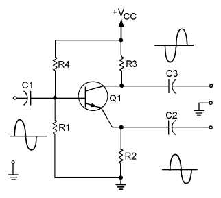
Figure 1-27.—Single-stage transistor phase splitter.
C1 is the input signal coupling capacitor and couples the input signal to the base of Q1. R1 develops
the input signal. R2 and R3 develop the output signals. R2 and R3 are equal resistances to provide equal
amplitude output signals. C2 and C3 couple the output signals to the next stage. R4 is used to provide
proper bias for the base of Q1.
This phase splitter is actually a single transistor combining the qualities of the common-emitter and
common-collector configurations. The output signals are equal in amplitude of the input signal, but are
180º out of phase from each other.
If the output signals must be larger in amplitude than the input signal, a circuit such as that shown in
figure 1-28 will be used.
Figure 1-28 shows a two-stage phase splitter. C1 couples the input signal to the base of Q1. R1
develops the input signal and provides bias for the base of Q1. R2 provides bias and temperature stability
for Q1. C2 decouples signals from the emitter of Q1. R3 develops the output signal of Q1. Since Q1 is
configured as a common-emitter amplifier, the output signal of Q1 is 180º out of phase with the input
signal and larger in amplitude. C3 couples this output signal to the next stage through R4. R4 allows only
a small portion of this output signal to be applied to the base of Q2. R5 develops the input signal and
provides bias for the base of Q2. R6 is used for bias and temperature stability for Q2. C4 decouples
signals from the emitter of Q2. R7 develops the output signal from Q2. Q2 is configured as a
common-emitter amplifier, so the output signal is 180º out of phase with the input signal to Q2 (output
signal from Q1). The input signal to Q2 is 180º out of phase with the original input signal, so the output
from Q2 is in phase with the original input signal. C5 couples this output signal to the next stage. So the
circuitry shown provides two output signals that are 180º out of phase with each other. The output signals
are equal in amplitude with each other but larger than the input signal.