3-37
You have now seen how an operational amplifier can be used in a circuit as an adder, a summing
amplifier, and a scaling amplifier.
Difference Amplifier (Subtractor)
A difference amplifier will produce an output based on the difference between the input signals. The
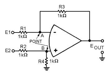
subtractor circuit shown in figure 3-25 will produce the following output:
Figure 3-25.—Subtractor circuit.
Normally, difference amplifier circuits have the ratio of the inverting input resistor to the feedback
resistor equal to the ratio of the noninverting input resistors. In other words, for figure 3-25:
and, by inverting both sides:
For ease of explanation, in the circuit shown in figure 3-25 all the resistors have a value of 1 kilohm,
but any value could be used as long as the above ratio is true. For a subtractor circuit, the values of R1
and R3 must also be equal, and therefore, the values of R2 and R4 must be equal. It is NOT necessary that
the value of R1 equal the value of R2.
Using figure 3-25, assume that the input signals are:
The output signal should be: