2-33
ADEQUATE BANDPASS is accomplished by optimum coupling in the rf transformer or by the use
of a SWAMPING RESISTOR.
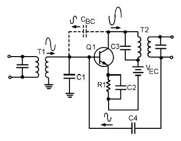
NEUTRALIZATION in an rf amplifier provides feedback (usually positive) to overcome the
effects caused by the base-to-collector interelectrode capacitance.
ANSWERS TO QUESTIONS Q1. THROUGH Q42.
A-1.
The difference between the upper and lower frequency limits of an amplifier.
A-2.
The half-power points of a frequency-response curve. The upper and lower limits of the band f
frequencies for which the amplifier is most effective.
A-3.
(A) f2 = 80 kHz, f1 = 30 kHz, BW = 50 kHz (B) f2 = 4 kHz, f1 = 2 kHz, BW = 2 kHz
A-4.
The capacitance and inductance of the circuit and the interelectrode capacitance of the transistor.
A-5.
Negative (degenerative) feedback.
A-6.
It decreases.
A-7.
It increases.
A-8.
The capacitance of the circuit.
A-9.
Peaking coils.
A-10.
The relationship of the components to the output-signal path.
A-11.
Combination peaking.
A-12.
The coupling capacitor (C3).