3-48
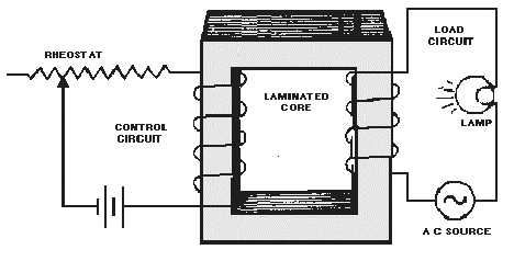
Figure 3-32.—A simple saturable-core reactor circuit.
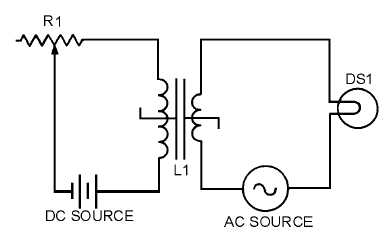
The schematic diagram of this circuit is shown in figure 3-33. L1 is the schematic symbol for a
saturable-core reactor. The control winding is shown with five loops, and the load winding is shown with
three loops. The double bar between the inductors stands for an iron core, and the symbol that cuts across
the two windings is a saturable-core symbol indicating that the two windings share a saturable core.
Figure 3-33.—Schematic diagram of a simple saturable-core reactor.
Now that you have seen the basic operation of a saturable-core reactor, there is one other idea to
discuss before moving on to the circuitry of a magnetic amplifier. There is a point upon the magnetization
curve where the saturable-core reactor should be operated. The ideal operating point is the place in which
a small increase in control current will cause a large increase in output power and a small decrease in
control current will cause a large decrease in output power. This point is on the flattest portion of the
permeability curve (after its peak).
Figure 3-34 shows the magnetization and permeability curves for a saturable-core reactor with the
ideal operating point (point "O") indicated. Notice point "O" on the magnetization curve. The portion of
the magnetization curve where point "O" is located is called the KNEE OF THE CURVE. The knee of the
curve is the point of maximum curvature. It is called the "knee" because it looks like the knee of a leg that
is bent. Saturable-core reactors and magnetic amplifiers should be operated on the knee of the
magnetization curve.


