4-16
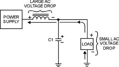
Figure 4-12.—Voltage drops in an inductive filter.
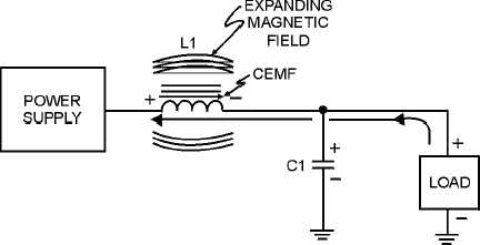
Now refer to figure 4-13. When the current starts to flow through the coil, an expanding magnetic
field builds up around the inductor. This magnetic field around the coil develops the CEMF that opposes
the change in current. When the rectifier current decreases, as shown in figure 4-14, the magnetic field
collapses and again cuts the turns (windings) of wire, thus inducing current into the coil. This additional
current merges with the rectifier current and attempts to keep it at its original level.
Figure 4-13.—Inductive filter (expanding field).