2-29
Now that we have analyzed the basic transistor amplifier in terms of bias, class of operation, and
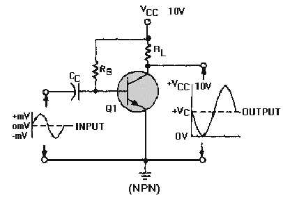
circuit configuration, let's apply what has been covered to figure 2-12. A reproduction of figure 2-12 is
shown below for your convenience.
This illustration is not just the basic transistor amplifier shown earlier in figure 2-12 but a class A
amplifier configured as a common emitter using fixed bias. From this, you should be able to conclude the
following:
Because of its fixed bias, the amplifier is thermally unstable.
Because of its class A operation, the amplifier has low efficiency but good fidelity.
Because it is configured as a common emitter, the amplifier has good voltage, current, and power
gain.
In conclusion, the type of bias, class of operation, and circuit configuration are all clues to the
function and possible application of the amplifier.
Q26.
What are the three transistor configurations?
Q27.
Which transistor configuration provides a phase reversal between the input and output signals?
Q28.
What is the input current in the common-emitter circuit?
Q29.
What is the current gain in a common-base circuit called?
Q30.
Which transistor configuration has a current gain of less than 1?
Q31.
What is the output current in the common-collector circuit?
Q32.
Which transistor configuration has the highest input resistance?
Q33.
What is the formula for GAMMA (
g
)?