3-6
Since a half-wave rectifier conducts once for each full cycle of input voltage, the frequency of the
pulses is the same as the frequency of the input sine wave. The output pulse frequency is called RIPPLE
FREQUENCY. If the rectifier circuit is supplied power from a 60-hertz ac line voltage, 60 pulses of load
current will occur each second. Therefore, THE RIPPLE FREQUENCY OF A HALF-WAVE
RECTIFIER IS THE SAME AS THE LINE FREQUENCY.
If a series of current pulses like those obtained from a half-wave rectifier is applied to a load
resistance, an average amount of power will be dissipated over a given period of time. This average dc
power is determined by the amplitude of the pulses and the time delay between pulses. The higher the
peak amplitude of the pulses or the less the time between pulses, the greater the average dc power
supplied to the load. To determine average dc voltage (Eavg), it is necessary to know the average value of
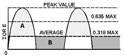
the pulses and the peak value of load voltage. This is illustrated in figure 3-7.
Figure 3-7.—Peak and average values for a half-wave rectifier.
Since current and voltage waveforms in a half-wave rectifier circuit are essentially half sine waves,
we can develop a conversion factor. The formula for average value was discussed earlier in NEETS,
module 2. By now you should know that the average value for a full sine wave is .637 times its peak or
maximum value. Therefore, if you want the average value of a half-wave rectifier output, you should
multiply half the value of .637 (.318) times the peak or maximum voltage, as expressed in the following
equation:
Eavg (the average load voltage) = .318 × Emax
Where:
Emax = The peak value of the load voltage pulse
In most applications the drop across the rectifier tube is small compared to the load voltage, so we
can assume Emax in our equation to be the same as the peak value of the input sine wave.
Since the load current has the same wave shape as the load voltage, we can modify the equation so
that it applies to the load current. Thus,
Iavg (the average load current) = .318 × Imax
Where:
Imax = The peak load current
If a line is drawn through the rectified waveform at a point that is 0.318 of the distance from zero to
maximum, the waveform will be divided so that area A is equal to area B (fig. 3-7). Therefore, current or