3-50
Signal tracing is done by observing the waveform at the input and output of each part of a circuit. It
is the method used to localize trouble in a circuit.
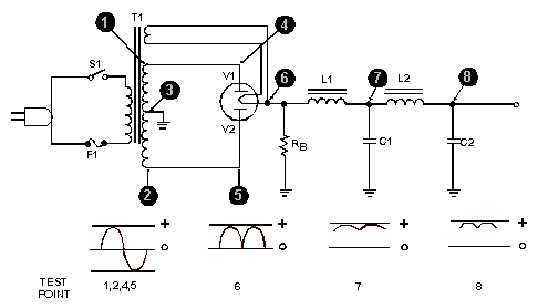
Let's review what each part of a good power supply does to the signal, as shown in figure 3-50. The
ac voltage is brought in from the power line through the line cord. This voltage is connected to the
primary of the transformer through the ON-OFF switch (S1). At the secondary winding of the
transformer (points 1 and 2), the scope shows you a picture of the stepped-up voltage developed across
each half of the secondary winding—the picture is that of a complete sine wave. Each of the two stepped-
up voltages is connected between ground and one of the two plates of the rectifier tube. At the two
rectifier plates (points 4 and 5) there is still no change in the shape of the stepped-up voltage the scope
picture still shows a complete sine wave.
Figure 3-50.—Complete power supply (without regulator).
However, when you look at the scope pattern for point 6 (the voltage at the rectifier heater), you see
the wave shape for pulsating direct current. This pulsating dc is fed through the first choke (L1) and filter
capacitor (C1), which remove a large part of the ripple or "hum," as shown by the waveform for point 7.
Finally, the dc voltage is fed through the second choke (L2) and filter capacitor (C2), which remove
nearly all of the remaining ripple. See the waveform for point 8, which shows almost no visible ripple.
You now have almost pure dc.
No matter what power supplies you may encounter in the future, they all do the same thing—they
change ac voltage into dc voltage.
COMPONENT PROBLEMS
The following paragraphs will give you an indication of troubles that occur with many different
electronic circuit components.
Tube Troubles
The symptoms of tube trouble will vary with every type of circuit and each type of tube. However,
the problems that can develop with a tube are common to every tube. Here are the five possible tube


