2-8
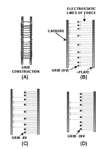
Figure 2-8.—Grid operation in a remote-cutoff tube.
In view B, the control grid is at zero potential (0 volts). Just as in the sharp-cutoff tube, electrons
leave the cathode and travel along the lines of electrostatic attraction, through the spaces between the grid
wires to the plate. In view C, a bias voltage of -6 volts is applied to the grid. Because of the close spacing
of the grid wires at the ends of the grid, electrostatic lines of force at the ends are effectively terminated.
The lines of force can only pass between the widely spaced grid wires closer to the center of the grid.
In view D, the same negative potential -20 volts) is applied to the grid that caused the conventional
sharp-cutoff tube discussed earlier to go into cutoff. This voltage is high enough to terminate most of the
electrostatic lines of force on the grid wire. But, because of the wide spacing between the center grid
wires, some electrostatic lines of force are still able to pass between the center grid wires and reach the
cathode. Conduction will still occur in the tube, but at a reduced level. If the grid is driven even more
negative, lines of force will be blocked from reaching the cathode, except at the very center of the grid.
As you can see, the remote-cutoff tube, by its ability to reduce gain (conduction), handles large signals
without going into cutoff. A variable-mu tube such as a 6SK7 with -3 volts applied to the grid will have a
transconductance of about 2000 (µ) mhos. If the grid is driven to -35 volts, the transconductance of the
tube will decrease to 10 (µ) mhos. This same increase in negative-grid voltage would have driven a
conventional tube into cutoff long before the grid reached -35 volts.


