1-33
The capacitor, then, can be said to regulate the current flow through the bias resistor. This action is
considered as BYPASSING or eliminating the effect of the ac input signal in the cathode. For all
practical purposes, you can assume that ac flows through the capacitor to ground. But, remember, ac only
appears to flow across a capacitor. In reality the ac signal is shunted around the capacitor.
There are two disadvantages associated with cathode biasing. To maintain bias voltage continuously,
current must flow through the tube, and plate voltage will never be able to reach the maximum value of
the source voltage. This, in turn, limits the maximum positive output for a negative input signal
(remember the 180º inversion). In addition, maximum plate voltage is decreased by the amount of
cathode-biasing voltage. What this means is that you can't get something for nothing. If the cathode is
biased at +20 volts, this voltage must be subtracted from the plate voltage. As an example, consider a
triode with a 10,000 ohm plate resistor and a +300 volts dc source voltage. If a current of 2 milliamperes
flows through the tube under quiescent conditions, 20 volts are dropped across the plate-load resistor. The
maximum plate voltage is then 300 volts - 20 volts = 280 volts dc. Now, consider the 20-volt dropped
across the cathode resistor. Plate voltage becomes 280 volts - 20 volts = 260 volts. To understand this a
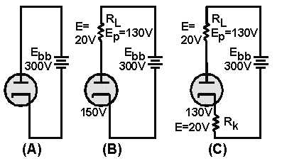
little more thoroughly, look at figure 1-24. In view A, the source voltage is 300 volts dc. There are two
ways that this voltage can be looked at; either the plate is at +300 volts and the cathode is at 0 volts
(ground), or the plate is at +150 volts and the cathode is at -150 volts. In electronics, it is common
practice to assume that the plate is at +300 volts while the cathode is at 0 volts. To simplify this
discussion, we will assume that the plate is at +150 volts, and the cathode is at -150 volts. The potential
difference between the plate and the cathode is 300 volts. If a plate-load resistor is installed, as shown in
view B, 20 volts are dropped by R
L. The potential difference between the plate and the cathode is now
280 volts. In view C, Rk has now been placed in the same circuit. Rk drops 20 volts. Therefore, the effect
of cathode biasing is to reduce the maximum positive signal that the circuit can produce. In this case, the
maximum positive signal has been reduced by 20 volts. Despite these disadvantages, cathode biasing has
two main advantages. It is simple and economical.
Figure 1-24.—Loss due to cathode biasing.
Grid-Leak Biasing
The second type of self-biasing to be discussed is GRID-LEAK BIAS. As the name implies, bias
voltage is developed in the grid leg portion of the circuit. Bias voltage in this type of biasing is derived by
allowing the positive input signal to draw grid current through a circuit made up of a resistor and a
capacitor. There are two types of grid-leak bias commonly in use: SHUNT TYPE and SERIES TYPE.
Because shunt type grid-leak biasing is the simplest, we will discuss it first. Figure 1-25 depicts a
simplified triode circuit using the shunt-type grid-leak biasing. Before we begin the explanation of shunt