3-5
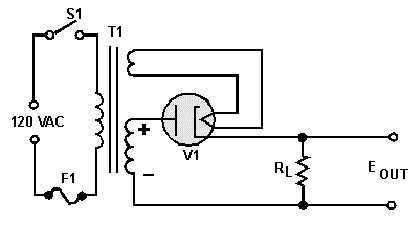
Figure 3-5.—Half-wave rectifier circuit.
You will better understand the operation of the half-wave rectifier circuit if it is redrawn in the form
of a simplified series circuit. As you can see in figure 3-6, the diode (V1) and load resistor (RL) are in
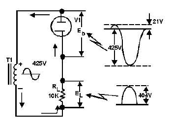
series with the secondary winding of the transformer. During the positive alternation of the input, as the
voltage in the secondary winding increases, the current through diode (V1) and load resistor (RL)
increases. Since the diode tube and the load resistor form a series circuit, the same current flows through
both the tube and the resistor. This current produces a voltage drop across the tube and the load resistor,
which have polarities as shown. Since the plate resistance of the tube is only about 500 ohms and the
resistance of the load resistor is 10,000 ohms, approximately 95 percent of the applied 425 volts is
dropped across the load resistor (425 × .95 = 404 V) and 5 percent (425 × .05 = 21 V) across the tube.
Figure 3-6.—Simplified half-wave rectifier circuit and waveforms.
During the negative half of the alternation of input voltage, the tube cannot conduct and no current
flows in the circuit. Since there is no current flow through RL, the load voltage remains at zero volts
throughout the negative alternation. During this time the entire negative alternation is felt across the tube.
The reason for this is derived from Kirchhoff's law, which states:
EL + Eb = Ea
The sum of the load voltage and diode voltage equals the applied voltage.