4-7
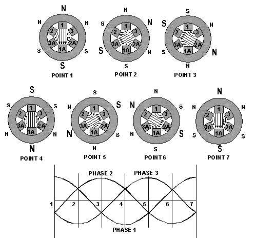
Figure 4-5.—Three-phase rotating-field polarities and input voltages.
The results of this analysis are shown for voltage points 1 through 7 in figure 4-5. At point 1, the
magnetic field in coils 1-1A is maximum with polarities as shown. At the same time, negative voltages
are being felt in the 2-2A and 3-3A windings. These create weaker magnetic fields, which tend to aid the
1-1A field. At point 2, maximum negative voltage is being felt in the 3-3A windings. This creates a strong
magnetic field which, in turn, is aided by the weaker fields in 1-1A and 2-2A. As each point on the
voltage graph is analyzed, it can be seen that the resultant magnetic field is rotating in a clockwise
direction. When the three-phase voltage completes one full cycle (point 7), the magnetic field has rotated
through 360º .
Q6.
What is the major difference between a two-phase and a three-phase stator?
ROTOR BEHAVIOR IN A ROTATING FIELD
For purposes of explaining rotor movement, let's assume that we can place a bar magnet in the center
of the stator diagrams of figure 4-5. We'll mount this magnet so that it is free to rotate in this area. Let's
also assume that the bar magnet is aligned so that at point 1 its south pole is opposite the large N of the
stator field.
You can see that this alignment is natural. Unlike poles attract, and the two fields are aligned so that
they are attracting. Now, go from point 1 through point 7. As before, the stator field rotates clockwise.
The bar magnet, free to move, will follow the stator field, because the attraction between the two fields