1-6
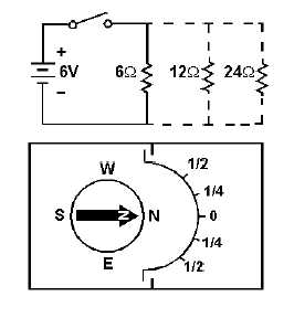
Figure 1-3.—A simple meter from a compass.
This is, in fact, the way the first GALVANOMETERS were developed. A galvanometer is an
instrument that measures small amounts of current and is based on the electromagnetic principle. A
galvanometer can also use the principles of electrodynamics, which will be covered later in this topic.
The meter in figure 1-3 is not very practical for electrical measurement. The amount the compass
needle swings depends upon the closeness of the compass to the conductor carrying the current, the
direction of the conductor in relation to magnetic north, and the influence of other magnetic fields. In
addition, very small amounts of current will not overcome the magnetic field of the Earth and the needle
will not move.
Q4. How does a compass react when placed close to a current carrying conductor?
Q5. If the amount of current in the conductor changes, what happens to the magnetic field around the
conductor?
Q6. How does the compass needle react to a decreased magnetic field?
PERMANENT-MAGNET MOVING-COIL MOVEMENT
The compass and conducting wire meter can be considered a fixed-conductor moving-magnet device
since the compass is, in reality, a magnet that is allowed to move. The basic principle of this device is the
interaction of magnetic fields-the field of the compass (a permanent magnet) and the field around the
conductor (a simple electromagnet).
A permanent-magnet moving-coil movement is based upon a fixed permanent magnet and a coil of
wire which is able to move, as in figure 1-4. When the switch is closed, causing current through the coil,
the coil will have a magnetic field which will react to the magnetic field of the permanent magnet. The
bottom portion of the coil in figure 1-4 will be the north pole of this electromagnet. Since opposite poles
attract, the coil will move to the position shown in figure 1-5.