1-52
Moving-Disk Frequency Meter
Moving-disk frequency meters are most commonly out-of-circuit meters. They can be used to spot
check the frequency of power sources or equipment signals.
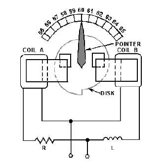
A moving-disk frequency meter is shown in figure 1-48. One coil tends to turn the disk clockwise,
and the other, counterclockwise. Magnetizing coil A is connected in series with a large value of
resistance. Coil B is connected in series with a large inductance and the two circuits are supplied in
parallel by the source.
Figure 1-48.—Simplified diagram of a moving-disk frequency meter.
For a given voltage, the current through coil A is practically constant. However, the current through
coil B varies with the frequency. At a higher frequency the inductive reactance is greater and the current
through coil B is less; the reverse is true at a lower frequency. The disk turns in the direction determined
by the stronger coil.
A perfectly circular disk would tend to turn continuously. This is not desirable, and so the disk is
constructed so that it will turn only a certain amount clockwise or counterclockwise about the center
position, which is commonly marked 60 hertz on commercial equipment. To prevent the disk from
turning more than the desired amount, the left half of the disk is mounted so that when motion occurs, the
same amount of disk area will always be between the poles of coil A. Therefore, the force produced by
coil A to rotate the disk is constant for a constant applied voltage. The right half of the disk is offset, as
shown in the figure. When the disk rotates clockwise, an increasing area will come between the poles of
coil B; when it rotates counterclockwise, a decreasing area will come between the poles of coil B. The
greater the area between the poles, the greater will be the disk current and the force tending to turn the
disk.
If the frequency applied to the frequency meter should decrease, the reactance offered by L would
decrease and the field produced by coil B would increase. The field produced by coil A would remain the
same. Thus, the force produced by coil B would tend to move the disk and the pointer counterclockwise