2-4
device is connected in parallel, current will simply flow around the protection device and continue in the
circuit.
A circuit protection device operates by opening and interrupting current to the circuit. The opening
of a protection device shows that something is wrong in the circuit and should be corrected before the
current is restored. When a problem exists and the protection device opens, the device should isolate the
faulty circuit from the other unaffected circuits, and should respond in time to protect unaffected
components in the faulty circuit. The protection device should NOT open during normal circuit operation.
The two types of circuit protection devices discussed in this chapter are fuses and circuit breakers.
Fuses
A fuse is the simplest circuit protection device. It derives its name from the Latin word "fusus,"
meaning "to melt." Fuses have been used almost from the beginning of the use of electricity. The earliest
type of fuse was simply a bare wire between two connections. The wire was smaller than the conductor it
was protecting and, therefore, would melt before the conductor it was protecting was harmed. Some
"copper fuse link" types are still in use, but most fuses no longer use copper as the fuse element (the part
of the fuse that melts). After changing from copper to other metals, tubes or enclosures were developed to
hold the melting metal. The enclosed fuse made possible the addition of filler material, which helps to
contain the arc that occurs when the element melts.
For many low power uses, the finer material is not required. A simple glass tube is used. The use of a
glass tube gives the added advantage of being able to see when a fuse is open. Fuses of this type are
commonly found in automobile lighting circuits.
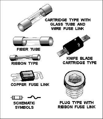
Figure 2-1 shows several fuses and the symbols used on schematics.
Figure 2-1.—Typical fuses and schematic symbols.